Latest
News
The Inaugural
Type 3 Invasion is coming up! Be there on August 17th
& 18th, 2002.
 |
For more information about the Invasion,
please visit the "Official" Invasion 2002 Site at: www.geocities.com/menacefye/invasion.html
There are "Official" Invasion t-shirt available.
Just go to my Type 3 Clothing page and click on the Invasion
T-shirt link or just click the text link.
There is a group of us planning to caravan
out to Parma for the Invasion in August. Watch this space for more
information about routes and timing. We will start the detailed planning
soon. |
Thermostat Parts
and Pictures
April 28, 2002
There has been a lot of discussion about
the thremostat linkages and funstion on the Type 3 List lately. I
happen to have both single and dual port versions of the linkage.
During a recent engine removal on my 66 Square, I took some pictures that
compare the two versions. They are posted here for your information.
Hope this helps.
Simply click on a thumbnail to see a large
version of the picture and them use your "BACK" button to get back here.
A. 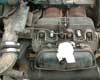 B.
B. 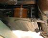 C.
C. 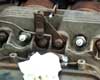 D.
D. 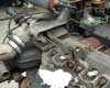 E.
E. 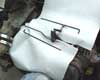
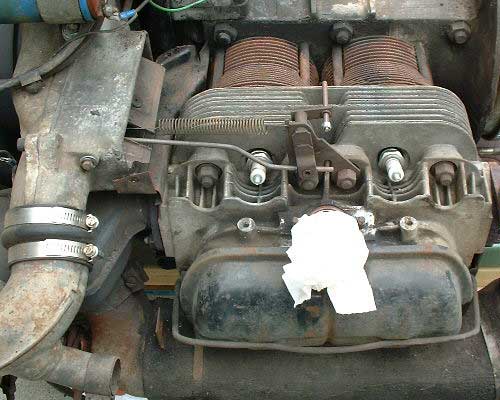
A. An overall shot of the linkages
for the thermostat system on my 66 Squareback with single port heads.
You can see the spring which is an important part of the system since it
pulls the flaps open should another element of the system fail.
B. A shot of the thermostat bellows.
This expands as the engine heats up, opening the fan shroud flaps.
The bellows and the bracket are common parts between the two systems and
common to the Type 1 Beetles.
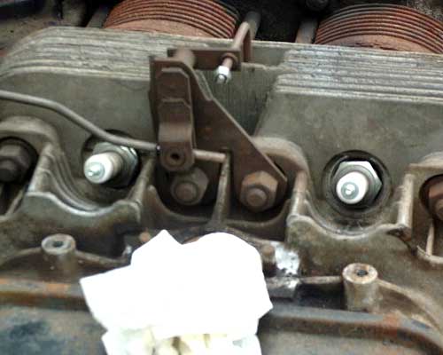
C. Here is a close up of the bellcrank
bracket that bolts to the head. This part is also common to both
the single and dual port systems. The bellcrank changes the expansion
of the bellows from vertical motion to horizontal motion to pull the flaps
open.
D. You can see the cooling flaps
in this shot. Look like a small garage door that is partial open.
Again these are common between the two systems. Be aware that although
the flaps are common, there are two versions of the magnesium fan housing
depending on which generator diameter you have.
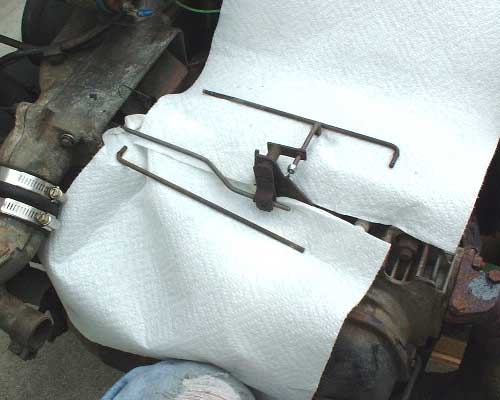
E. And finally, the only difference
between the two systems is the link rods. The parts that are installed
are the single port versions. The parts laying loose are the dual
port parts. Basically the horizontal leg of the vertical link is
longer on the single port version to reach to the bellcrank which is mounted
further away from the center of the engine on the single port. The
horizontal link has a z-bend in it to get it out to the right position.
This make sense from a OEM standpoint since the tooling changes required
to alter the rods would be the cheapest to make once the heads were changed.
Typical VW.

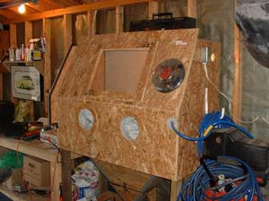
Sandblasting Cabinet
Plans
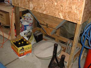
One of the truly useful tools I have in
my garage is my sandblasting cabinet. I orginially had a simple "blast
from a bucket" sandblaster. It worked fine, but I was dumping sand
out of my clothes and shoes for a week after using it. I was also
going through sand pretty fast. I decided I needed a cabinet to blast
in. In my case, I actually built my own cabinet. It has proven
to be a great help in the restoration and customization of my Type 3s.
I use it for stripping paint and rust from parts and for cleaning up bolts
and nuts and other parts. I just use sand in mine, but I am sure
I could run other kids of media. The total cost including the gloves
was under $75. This obviously does not include the cost of the air
compressor or the sandblasting gun.
I got around to taking some pictures and
sketching up some basic dimensioned plans. Thought they might be
useful to other T3ers/
Click on an image to see a larger version.
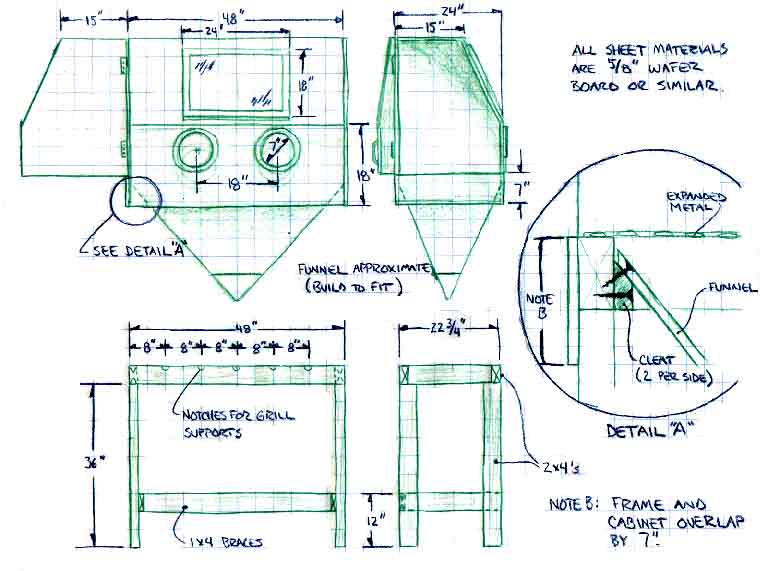
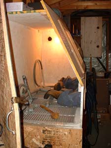
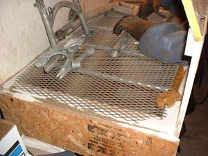
Couple of notes: I used electrical
(1/2", I think) electrical conduit for the grill supports. The actual
grill is a piece of expanded metal. My pick-up tube is also electrical
conduit (5/8", I think). It just runs down one corner of the funnel
to within a couple of inches of the bottom. I also sealed up all
of the seams on the inside with construction adhesive. Painting the
inside white is a big help. Having a lot of air available is a must.
My 6.5HP, 30 Gal Oilless Sears Craftsman compressor just keeps up.
It runs continuously, though. The other essential is dry air.
I have a micron level air water separator in line to the cabinet.
Without it the sand quickly turns to mud in the gun and clogs it up.
A good source of materials, including the
gloves, is Eastwood Company.
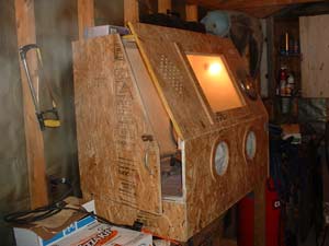
I originally did not have a Shop-Vac hooked
up and the visibility was bad due to dust. Had to stop every 10 minutes
or so and let things settle. You can see the hole I drilled
to hook up my Shop-Vac in one of the interior shots. It is near the
light. Visibility is greatly inproved with the vac on. Don't
have to stop at all now, except for when my trigger finger get sore. One
thing to make sure of though...... you need to have a bunch of vent holes
for the cabinet with the shop-vac hooked up. The first time I turned
on the vac, my gloves stood out stiff as a board and I could not
move them. Too much suction.
You can see the holes I added to mine to
the left of the window on the front face. One advantage of having
them there, I think, is that it sets up the airflow inside across the window
and helps with visibility.
Things I would change.....hmmmmmmm.
I think I would make it top loading rather
than end loading. I lose blast media everytime I open the door and
it is a bit messy. Might add a lip inside the door to minimize this.
I will be adding a second light on the inside. Too many shadows with
only one. My one light is on the non-door end. I will add one
near the door. Just worry about breaking it all the time while loading
parts. I also recommend getting a foot switch for the air.
My fingers get too sore with the trigger. I still need to make this
investment. Other than that I am very happy with the cabinet.
It was a minimum amount of materials and not tough to construct.
Hardest parts was fabbing the funnel on the bottom. Mine is particle
board. I would consider sheet metal the next time.
Making one big enough for a T3 fender would
be impressive, considering how long the fenders are. Might have to
have two funnels on the bottom in order to get the angle of repose right
for the media. This is the angle that the material will pile to if
piled free. The angle needs to be greater than this for the media
to flow down into the bottom.
I will eventually add this stuff to my
Technical Page.
|